Describe Downloads
| File | Download |
|---|---|
| DEScribe v3.7 by Dimension Engineering | Installer (for Windows) Documentation |
| DEScribe Beta v3.9 by Dimension Engineering | Installer (for Windows) Installer (for Mac) Installer (for Linux) |
| DEScribe Beta v3.9.9 by Dimension Engineering | Installer (for Windows) Installer (for Mac) Installer (for Linux) |
What's the wiring for my USB-serial converter?
| SyRen/Sabertooth/Kangaroo | USB-to-TTL Serial Converter |
|---|---|
| 0V | Ground |
| S1 | Transmit ("TX") Signal |
| S2 | Receive ("RX") Signal |
DEScribe FAQ
What are the SyRen/Sabertooth DIP switch settings for DEScribe?
1 and 2 OFF (Packet Serial mode)
4, 5, and 6 ON (address 128, optional but recommended)
What are the Kangaroo DIP switch settings for DEScribe?
1 ON (Digital Input mode)
Arduino Libraries
| Library | Download |
|---|---|
| Arduino Libraries for SyRen/Sabertooth Serial (includes examples) v1.5 by Dimension Engineering | Installer (for Windows) or .zip File Documentation SyRen/Sabertooth Packet Serial USB Sabertooth Packet Serial Sabertooth Simplified Serial SyRen Simplified Serial |
| Arduino Examples for SyRen/Sabertooth R/C Mode v1.1 by Dimension Engineering | .zip File |
| Arduino Library for Kangaroo Packet Serial (includes examples) v1.0.6 by Dimension Engineering | Installer (for Windows) or .zip File Documentation |
| Comments, questions, suggestions? Let us know! |
Which mode should I use with my motor driver?
| Mode | Advantages | Disadvantages |
|---|---|---|
| Packet Serial | Most powerful Control up to 8 SyRen/Sabertooth per pin SyRen and Sabertooth use the same 8-bit commands Commands are checksummed for reliability Setting commands for ramp time, deadband, etc. | V2 controllers: Baud rate changes require a command V1 controllers: Autobaud requires low startup transients |
| Plain Text Serial | Extremely beginner-friendly Control up to 4 Sabertooth per pin Commands can be checksummed for reliability Reasonably powerful | For USB Sabertooth drivers only |
| Simplified Serial | Beginner-friendly Fast single byte commands Baud rate settable with DIP switches | 7-bit on Sabertooth No checksumming Requires one pin per SyRen or Sabertooth |
| R/C Microcontroller | Control each motor with servo commands Use 3-argument init: servo.attach(pin, 1000, 2000); Compatible with R/C versions of Sabertooth Servo library comes with Arduino software 0°-90° (1000-1500 μs) reverses 90°-180° (1500-2000 μs) goes forward 90° (1500 μs) stops | Requires one pin per motor Not as precise, sensitive to timing jitter |
Packet Serial FAQ
Which motor drivers use autobauding in packet serial?
V1 motor drivers use autobauding. The list of V1 motor drivers is as follows:
- SyRen 10
- SyRen 25
- Sabertooth 2X5
- Sabertooth 2X10
- Sabertooth 2X25 V1
V2 and newer motor drivers store their baud rate in an EEPROM setting (the factory default is 9600).
I have a V1 motor driver and the Sweep packet serial sample only moves forward and stops at 9600.
We've run into this with the Arduino Uno and Sabertooth 2X5. There is a startup transient on the Uno that the Sabertooth sees as a very fast autobaud character. As a result it autobauds at its maximum baud rate, 38400. Changing the Serial.begin(9600); line to Serial.begin(38400); got things running for us.
Calculators
A beginner’s guide to accelerometers
What is an accelerometer?
An accelerometer is an electromechanical device that will measure acceleration forces. These forces may be static, like the constant force of gravity pulling at your feet, or they could be dynamic - caused by moving or vibrating the accelerometer.
What are accelerometers useful for?
By measuring the amount of static acceleration due to gravity, you can find out the angle the device is tilted at with respect to the earth. By sensing the amount of dynamic acceleration, you can analyze the way the device is moving. At first, measuring tilt and acceleration doesn't seem all that exciting. However, engineers have come up with many ways to make really useful products with them.
An accelerometer can help your project understand its surroundings better. Is it driving uphill? Is it going to fall over when it takes another step? Is it flying horizontally or is it dive bombing your professor? A good programmer can write code to answer all of these questions using the data provided by an accelerometer. An accelerometer can help analyze problems in a car engine using vibration testing, or you could even use one to make a musical instrument.
In the computing world, IBM and Apple have recently started using accelerometers in their laptops to protect hard drives from damage. If you accidentally drop the laptop, the accelerometer detects the sudden freefall, and switches the hard drive off so the heads don't crash on the platters. In a similar fashion, high g accelerometers are the industry standard way of detecting car crashes and deploying airbags at just the right time.
How do accelerometers work?
There are many different ways to make an accelerometer! Some accelerometers use the piezoelectric effect - they contain microscopic crystal structures that get stressed by accelerative forces, which causes a voltage to be generated. Another way to do it is by sensing changes in capacitance. If you have two microstructures next to each other, they have a certain capacitance between them. If an accelerative force moves one of the structures, then the capacitance will change. Add some circuitry to convert from capacitance to voltage, and you will get an accelerometer. There are even more methods, including use of the piezoresistive effect, hot air bubbles, and light.
What things should I consider when buying an accelerometer?
Analog vs digital - First and foremost, you must choose between an accelerometer with analog outputs or digital outputs. This will be determined by the hardware that you are interfacing the accelerometer with. Analog style accelerometers output a continuous voltage that is proportional to acceleration. E.g. 2.5V for 0g, 2.6V for 0.5g, 2.7V for 1g. Digital accelerometers usually use pulse width modulation (PWM) for their output. This means there will be a square wave of a certain frequency, and the amount of time the voltage is high will be proportional to the amount of acceleration.
If you are using a BASIC Stamp, or any other microcontroller with purely digital inputs, you will most likely need to go for a digital output accelerometer. The disadvantage here is that it requires you to use the timing resources of the microcontroller to measure the duty cycle, as well as performing a computationally intensive division operation.
If you are using a PIC/AVR/OOPIC/Javelin with analog inputs, or a completely analog based circuit, analog is almost always the best way to go. Depending on the compiler, measuring analog acceleration can be as simple as acceleration=read_adc(); and can be done in a few microseconds.
Number of axes - For most projects, two is enough. However, if you want to attempt 3d positioning, you will need a 3 axis accelerometer, or two 2 axis ones mounted at right angles.
Maximum swing - If you only care about measuring tilt using earth's gravity, a ±1.5g accelerometer will be more than enough. If you are going to use the accelerometer to measure the motion of a car, plane or robot, ±2g should give you enough headroom to work with. For a project that experiences very sudden starts or stops, you will need one that can handle ±5g or more.
Sensitivity - Generally speaking, the more sensitivity the better. This means that for a given change in acceleration, there will be a larger change in signal. Since larger signal changes are easier to measure, you will get more accurate readings.
Bandwidth - This means the amount of times per second you can take a reliable acceleration reading. For slow moving tilt sensing applications, a bandwidth of 50Hz will probably suffice. If you intend to do vibration measurement, or control a fast moving machine, you will want a bandwidth of several hundred Hz.
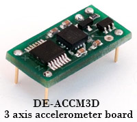
Impedance/buffering issues - This is by far the single most common source of problems in projects involving analog accelerometers, because so few people thoroughly read the required documentation. Both PIC and AVR datasheets specify that for A-D conversion to work properly, the connected device must have an output impedance under 10kΩ. Unfortunately, Analog Devices' analog accelerometers have an output impedance of 32kΩ. The solution to this is to use a low input offset rail to rail op amp as a buffer to lower the output impedance. As far as we know, the DE-ACCM is the only accelerometer solution that takes care of this problem for you.
Where can I find more information on accelerometers?
Texas Instruments has a great accelerometer guide, including how to do some of the necessary math.
The DE-ACCM datasheet has several examples of how you can use accelerometer readings to determine tilt and acceleration values.
If you really want to get into the hardcore low level details of accelerometers, and want to try soldering surface mount packages, Analog Devices has a huge selection of datasheets covering both analog and digital PWM style devices.
A beginner’s guide to switching regulators
What is wrong with a linear regulator?
Linear regulators are great for powering very low powered devices. They are easy to use and cheap, and therefore are very popular. However, due to the way they work, they are extremely inefficient.
A linear regulator works by taking the difference between the input and output voltages, and just burning it up as waste heat. The larger the difference between the input and output voltage, the more heat is produced. In most cases, a linear regulator wastes more power stepping down the voltage than it actually ends up delivering to the target device!
With typical efficiencies of 40%, and reaching as low as 14%, linear voltage regulation generates a lot of waste heat which must be dissipated with bulky and expensive heatsinks. This also means reduced battery life for your projects.
Even the new LDO (low drop-out) regulators are still inefficient linear regulators - they just give you more flexibility with input voltage drops.
How is a switching regulator better?
A switching regulator works by taking small chunks of energy, bit by bit, from the input voltage source, and moving them to the output. This is accomplished with the help of an electrical switch and a controller which regulates the rate at which energy is transferred to the output (hence the term “switching regulator”).
The energy losses involved in moving chunks of energy around in this way are relatively small, and the result is that a switching regulator can typically have 85% efficiency. Since their efficiency is less dependent on input voltage, they can power useful loads from higher voltage sources.
Switch-mode regulators are used in devices like portable phones, video game platforms, robots, digital cameras, and your computer.
Switching regulators are complex circuits to design, and as a result they aren’t very popular with hobbyists. However Dimension Engineering creates switching regulators that are even easier to use than linear regulators, because they use the same 3 pin form factor, but don’t require any external capacitors.
What can switching regulators do that linear regulators can't?
With high input voltages, driving loads over 200mA with a linear regulator becomes extremely impractical. Most people use a separate battery pack in these situations, so they have one battery pack for high voltage devices and one for low voltage devices. This means you have twice as many batteries to remember to charge, and twice the hassle! A switching regulator can easily power heavy loads from a high voltage, and save you from splurging on an additional battery pack.
Certain kinds of switching regulators can also step up voltage. Linear regulators cannot do this. Ever.
How do I tell if I need a switching regulator?
As a general rule of thumb, if your linear voltage regulation solution is wasting less than 0.5 watts of power, a switching regulator would be overkill for your project. If your linear regulator is wasting several watts of power, you most certainly want to replace it with a switcher! Here is how to calculate power losses:
The equation for wasted power in a linear regulator is:
Power wasted = (input voltage – output voltage) * load current
For example, let’s say you have a 12V lead-acid battery and you want to power a microcontroller that draws 5mA, and an ultrasonic rangefinder that draws 50mA. Both the microcontroller and the ultrasonic rangefinder run off of 5V. You use an LM7805 (a very common linear regulator) to get the voltage down to 5V from 12V.
Power wasted = (12V – 5V) * (0.050A + 0.005A) = 0.385W
0.385W is not too bad for power losses. The LM7805 can handle this without a big heatsink. You could get more battery life if you used a switching regulator, but in this case the power consumption is so low that the battery life will be very long anyway.
Now let’s expand on this example, and add two servos that draw an average of 0.375A each, and also run off of the 5V supply. How much power is wasted in a linear regulator now?
Power wasted = (12V – 5V) * (0.050A + 0.005A + 0.375A + 0.375A) = 5.635W
5.6 Watts is a lot of waste heat! Without a large heatsink the LM7805 would get so hot it would desolder itself or melt your breadboard or defeat Iceman. Even with the heatsink, 5.6W is also a lot of life to suck out of your battery for no reason. A switching regulator such as a DE-SW050 would be very useful in this case, and would reduce power losses to around 0.5W.
Is a switching regulator really worth 10+ bucks?
The final thing to consider is of course, cost. If your project is cheap and simple enough that a switching regulator would triple the cost of the entire project, then a switching regulator may be hard to justify. However if you are building a more advanced robot, airplane etc. and a switching regulator adds 15% to your cost, but gives you 35% more battery life, then it is a good deal right?
I am not stupid. I know you are just trying to sell your products. Why should I buy a switching regulator from you instead of from someone else?
Our regulators are light, small, efficient, have a wide input range, are clearly labeled and even easier to use than a linear regulator. They are also cheaper than other regulators with similar specifications. Plus unlike other companies, we won’t rip you off on shipping. We hate it when people do that to us!
Where can I find more information on switching regulators?
Try searching for “buck converter”, “boost converter” or “dc-dc converter” and you should find some good tutorials.
Dimension Engineering's BEC FAQ
What is a BEC?
BEC stands for Battery Eliminator Circuit. In the old days of electric flight you had to use a separate 4.8V battery pack to power your receiver and servos. As the hobby evolved, speed controls started to include Battery Eliminator Circuits to power your receiver and servos, allowing you to get rid of the extra receiver battery pack.
How does a BEC work?
A BEC is basically a step down voltage regulator. It will take your main battery voltage (e.g. 11.1 Volts) and reduce it down to ~5 Volts to safely power your receiver and servos.
What are the advantages of a BEC?
If you are flying electric, a BEC is better than a battery pack in nearly all cases. On average, the BEC will weigh 10-20 times less than a receiver battery pack! Then you have to take into account the hassle of charging the receiver pack. It is another battery you have to carry around along with another charger. Did you remember to charge it after the last time you flew? Uh-oh might want to double check that!
With a BEC, you only have to worry about charging your main flight pack and then you are guaranteed to have a safe flight.
Glow planes usually need a receiver pack, but the vast majority of electric planes out there are better off with a BEC.
I have a 3A BEC in my speed control - is that enough?
What is a switching BEC?
It is very common for speed controls to have BECs rated at 2 or 3A. However, what the manufacturers do not tell you is that this rating is only true for an input voltage of 6V. The BEC on your speed control is what engineers call a 'linear voltage regulator'. It works by burning up excess voltage and turning it into heat. The higher the input voltage, the more heat gets produced. If there is too much heat, then the BEC will either fry, or shut down! The result of this is that in real world situations, if you are running a 3S lithium battery pack, your ESC's BEC will only be able to provide about 0.5A before it overheats. At 4S, most ESC manufacturers don't recommend you use the BEC at all, or at best power two small servos. Dimension Engineering's BECs are a different type of voltage regulator - a switching voltage regulator. They do not care very much about what the input voltage is, and as such can provide your servos with their full current rating all the way up to 8S or more. For more information on the principles of a switching BEC, please visit our beginner's guide to switching regulators.
What are the pros and cons of internal BECs and external BECs?
Most speed controls nowadays have an internal 5V linear BEC. It is a nice cheap, simple solution that works very well at low voltages like 2S lithium and 6 cell NiCd packs. If you are flying a 2S lithium aircraft, stick with the internal linear BEC on your speed control because it will be cheaper. 3S lithium and above is where a switching BEC starts to pay off. Since the external switching BEC will work efficiently at higher voltages you will immediately notice your speed control running cooler. You will be able to run more and more powerful servos. You will be guaranteeing reliable power to your receiver and servos. If you have ever suddenly lost power to your receiver in flight, then an external switching BEC may be the answer to your problems.
Are there any other reasons to get an external BEC?
Some of the new Spektrum receivers draw significantly more current than a normal receiver, and are particularly sensitive to voltage fluctuations. An external switching BEC can help ensure your new receiver gets reliably powered. Our switching BECs also allow you to have a choice of output voltage - 5 volts or 6 volts.
I'm not using a speed control. Can I still use the BEC to give me a steady voltage?
By all means! Dimension Engineering BECs maintain all their specifications without a speed control attached. Be sure to cover or clip the BEC's ESC pins so they don't electrically contact anything.
5V or 6V?
One of the great things about an external switching BEC is that it allows you to choose your voltage output. Running at 5V gives you standard servo response. Running at 6V means more power will be delivered to your servos, so you will get more speed and torque. Running at 5V or 6V will depend on what you are flying, and how you personally like to fly. A simple parkflyer that isn't doing any complicated maneuvers will probably feel best at 5V. If you are doing complicated 3D aerobatics with sharp turns, you will probably appreciate the response 6V gives you. Helicopter flyers especially like the response 6V gives them on a tail servo. If you decide you want to run at 6V, make sure your servos can handle it. Most servos can, but some really tiny ones like the Hitec HS-50 will burn up at 6V.
How will a switching BEC affect my flight time?
Actually, it will barely make a difference to your flight time. Compared to your main motor, your receiver and servos barely draw much power at all. On a typical flight you can expect to have ~10 seconds less flying time if you have been using a receiver pack. If you have been using a speed control's linear BEC, then a switching BEC might get you ~10 seconds more flight time. Nothing really noticeable.
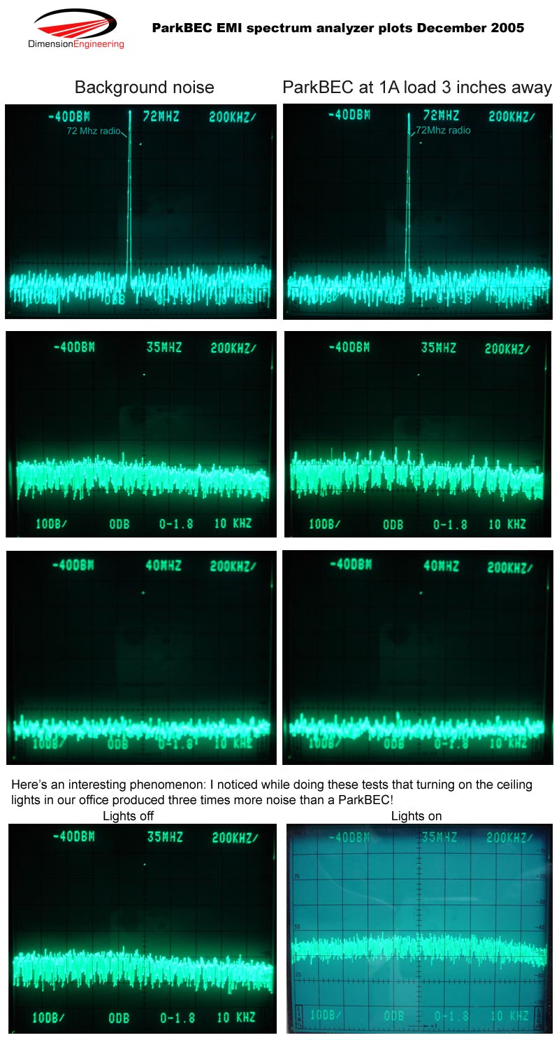
I heard that switching BECs can put out harmful radio interference, causing reduced range. Is this true?
This is true for a lot of the switching BECs on the market. This is because it is relatively easy to make a switching BEC that gives you 5V and powers your servos, but it is not easy to come up with a design that is free of radio interference. This takes hundreds of man hours, dozens of design revisions, expensive test equipment and extensive beta testing. At Dimension Engineering, we put the time, money and effort into developing BECs that do not radiate. As long as you keep the BEC at least 2 inches away from your receiver, antenna and other electronics, you will not experience any glitching. We guarantee it.
Can you help me pick out a BEC?
Here are some general guidelines for common configurations:
| Plane setup | Recommendation |
|---|---|
| Small planes with a 2S lithium pack Small planes with only 2 small analog servos and a 3S lithium pack | No external BEC needed |
| Parkflyers with 4 to 6 sub-micro analog servos e.g. HS-55, HS-56 and 3+S lithium packs Parkflyers with 4 HS-81 servos and 3+S lithium packs | ParkBEC |
| Small 3D/aerobatic flyers with 4 to 6 sub-micro analog servos e.g. HS-55, HS-56 and 3+S lithium packs Small 3D/aerobatic flyers with 4 HS-81 servos and 3+S lithium packs | ParkBEC 6V |
| Sport planes, glow conversions, larger 3d planes, planes with multiple high torque servos, HS-65 servos and/or digital servos. 3S to 8S lithium packs | SportBEC |
| Helicopter setup | Recommendation |
|---|---|
| Tiny coaxial helis (Blade CX, Lama) with 2S lithium packs | No external BEC needed |
| Micro helis with sub-micro analog servos e.g. HS-55, HS-56 and 3+S lithium packs. 3xHS-56, 1xS9650 and a 401 Gyro is an especially popular combo with ParkBEC 6V. | ParkBEC 6V |
| Micro / mini helicopters with 3S to 8S lithium battery packs, running high speed/torque servos and/or digital servos. e.g. HS-65, HS-635, S9451, S9550 | SportBEC |
| Big helicopters with battery packs 9S to 14S lithium (33.6V to 60V) | VHVBEC |
| Really big (60"+) helicopters with battery packs 9S to 14S lithium (33.6V to 60V) with 4 digital servos drawing peak currents >1A | Two VHVBECs in parallel |
Contact us if you still need help choosing a product!
Why should I get a BEC from Dimension Engineering when I can find a cheaper one elsewhere?
A critical difference between our BECs and our competitors' BECs is that our products are guaranteed to not cause radio interference. You can get a cheap imported BEC, but you'd just be paying 10 bucks to knock your plane out of the sky! Every manufacturer likes to boast that their BEC won't cause interference. We actually have the data to prove it. The #1 design criterion with all Dimension Engineering BECs is that they absolutely cannot put out any harmful interference. Other guys cut costs in ways that are downright scary.
Our BECs also have a throttle pass through system, which means you can use our BECs without snipping the red wire of your speed control.
Our higher powered BECs have the world's easiest to use 5V/6V selection system. Just flick the slide switch with your finger! There are no jumpers to lose or any complicated programming procedures. An LED will indicate whether you are in 5V or 6V mode.
Finally we have great customer support for our products. In the extremely unlikely event of a problem with your BEC, we will quickly get a replacement out to you. If you are confused on how to wire things up, send us an email and we will respond. Try doing that with an imported product!